 EN


Introduction
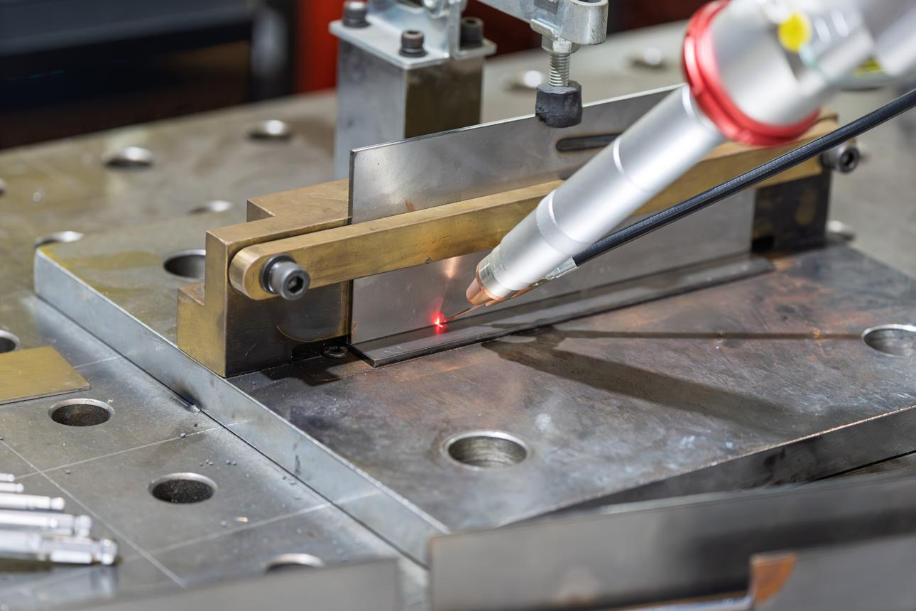
When laser welding thin metal parts, a stable welding process depends on more than the welding equipment itself. Workpiece positioning, joint fit, clamping pressure and welding access all influence the final result. Even small changes in the position of a thin component can affect the joint location, appearance and overall dimensions of the finished assembly.
A properly planned fixture helps maintain the relationship between components throughout the welding process. It also makes loading, unloading and repeated positioning easier to manage during production.
When evaluating laser welding machine, use representative parts and clearly defined production requirements. Reviewing actual samples and drawings before confirming a machine configuration helps identify fixture requirements and potential production problems at an early stage.
1. Part Datums
The first step in fixture planning is identifying the reference points used to position each workpiece. These reference points, commonly called datums, establish how the components should be aligned before welding begins.
For thin metal parts, the positioning method should be based on the actual product geometry. Flat surfaces, machined edges, holes and formed features may all serve as useful locating references, depending on the design.
A fixture should support the workpiece in a repeatable position without relying on inconsistent manual alignment. Locating pins, positioning blocks, side stops and supporting surfaces can help establish the required relationship between components.
However, the fixture design should not restrict necessary adjustments. If a part has variations in its cutting dimensions or forming shape, the positioning arrangement may need to accommodate these differences while maintaining the required joint location.
Before finalizing the fixture, review the product drawing and identify the critical dimensions that must remain consistent after welding. These dimensions should guide the selection of locating points and supporting structures.
2. Joint Fit
Joint fit is another important factor when preparing thin metal parts for laser welding. The distance between two components, their contact condition and their relative alignment can affect welding consistency.
If the joint gap varies from one sample to another, the welding result may also become less predictable. Poor contact can create uneven joint conditions, while excessive overlap or misalignment may affect the intended welding position.
During sample preparation, check the actual fit between the components rather than relying only on nominal drawing dimensions. Measure the relevant edges and compare several representative workpieces to understand the variation within the current production process.
Fixture contact surfaces should hold the components in the intended relationship without forcing them into an unnatural shape. If a part needs excessive pressure to achieve the required joint fit, investigate whether the original cutting, bending or forming process is contributing to the problem.
The acceptable joint gap and alignment tolerance should be confirmed through the product drawing, welding process requirements and sample testing. They should not be assumed to be identical for every material thickness or product structure.
3. Clamping
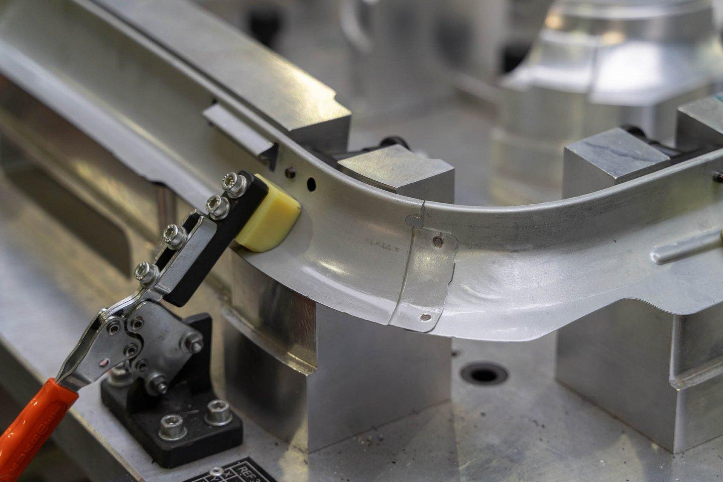
Clamping keeps thin metal components in position during welding, but excessive pressure can introduce another problem: deformation.
Thin sheets and lightweight formed parts may bend when subjected to uneven or concentrated clamping forces. This can change the joint position and affect the dimensions of the completed assembly.
A practical fixture should distribute holding forces across suitable contact areas. Support blocks and adjustable clamping points can help prevent unnecessary movement while reducing the risk of local deformation.
The location of each clamp also matters. Clamping too close to a welding joint may interfere with the welding path, while positioning clamps too far away may allow the workpiece to move during processing.
For products with several welding positions, consider whether the fixture can maintain stable support throughout the complete sequence. The arrangement should also allow operators to load and secure the components without unnecessary adjustments.
During trials, inspect the parts before and after clamping. Compare their dimensions and observe whether any visible bending or displacement occurs. These checks help determine whether the fixture pressure and support arrangement are suitable for the actual workpiece.
4. Weld Access
A fixture must hold the parts securely while leaving sufficient access for the welding process.
This requirement becomes particularly important when products contain narrow corners, folded edges, overlapping components or multiple joints. A clamp may provide excellent positioning but still prevent the welding head from reaching the required joint.
Before manufacturing a fixture, review the complete welding path against the product geometry. Consider the approach direction, the available working space and whether nearby fixture components could obstruct the operation.
For assemblies with multiple weld locations, check whether all positions can be reached without repeatedly removing and repositioning the workpiece. If different access directions are required, the fixture may need a different support arrangement or a planned repositioning sequence.
The welding head, protective components and other equipment-related clearances should also be considered. These requirements must be checked against the actual machine configuration rather than estimated from a product drawing alone.
A useful method is to review the fixture together with representative samples and the proposed welding sequence. This makes potential access problems easier to identify before production begins.
5. Unloading
Unloading is sometimes overlooked during fixture design, even though it directly affects production consistency.
A fixture should allow the completed assembly to be removed without bending thin components, disturbing other parts or damaging the finished weld area. If the product is difficult to release, operators may apply unnecessary force or change the position of the fixture during handling.
For repeated production, consider how the operator loads the individual components, establishes their reference positions, applies the clamps and removes the finished assembly.
The fixture should provide a clear and repeatable sequence. Where appropriate, locating features can help return the next workpiece to the same reference position after unloading.
It is also important to consider whether welding heat or repeated handling could affect the fixture's contact surfaces over time. Regular inspection of locating elements, support blocks and clamping components helps identify wear or changes that may influence positioning.
A practical production trial should include several consecutive loading and unloading cycles, not just one successful sample. This helps determine whether the fixture remains convenient and repeatable during normal operation.
6. Sample Review
The final fixture evaluation should be based on actual welded samples and agreed inspection criteria.
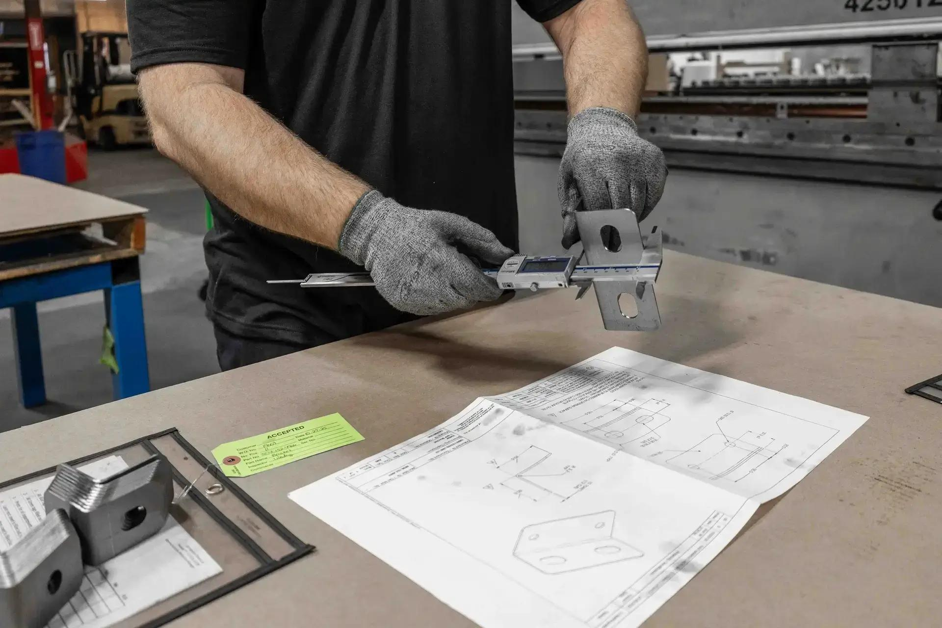
Start by checking the overall dimensions of the completed assembly. Compare critical distances, angles, flatness and component positions against the product drawing. For thin metal parts, pay particular attention to distortion around welded areas and any changes in the relationship between connected components.
Next, inspect the weld joints. Review their location, continuity and visible appearance according to the requirements of the specific product. Where necessary, additional joint-strength or other quality tests should be defined according to the intended application.
It is useful to record the fixture arrangement, workpiece references, clamping positions and welding sequence used during the sample trial. These records make it easier to compare different setups and identify the source of any dimensional variation.
The review should also cover repeatability. Several samples produced under the same agreed conditions provide a more useful basis for evaluation than a single finished part.
Acceptance criteria should be established before testing. Material specifications, part dimensions, joint requirements and inspection methods need to be agreed upon by both parties. Welding parameters and machine capabilities should be confirmed using the actual equipment documentation and trial results.
Conclusion
Fixture planning is an important part of preparing a reliable laser welding process for thin metal components. Correct positioning, suitable joint fit, balanced clamping, sufficient welding access and convenient unloading all contribute to production consistency.
Rather than selecting a fixture based only on general product descriptions, manufacturers should evaluate real workpieces, drawings and representative welded samples. The final arrangement should be confirmed against the actual machine configuration and mutually agreed quality requirements.
Send the drawings, material details, quality criteria and target output for an application review. Please contact Jinchun to review the requirements. Our team can assess your product structure and discuss a suitable laser welding solution based on your production needs.