 EN


Introduction
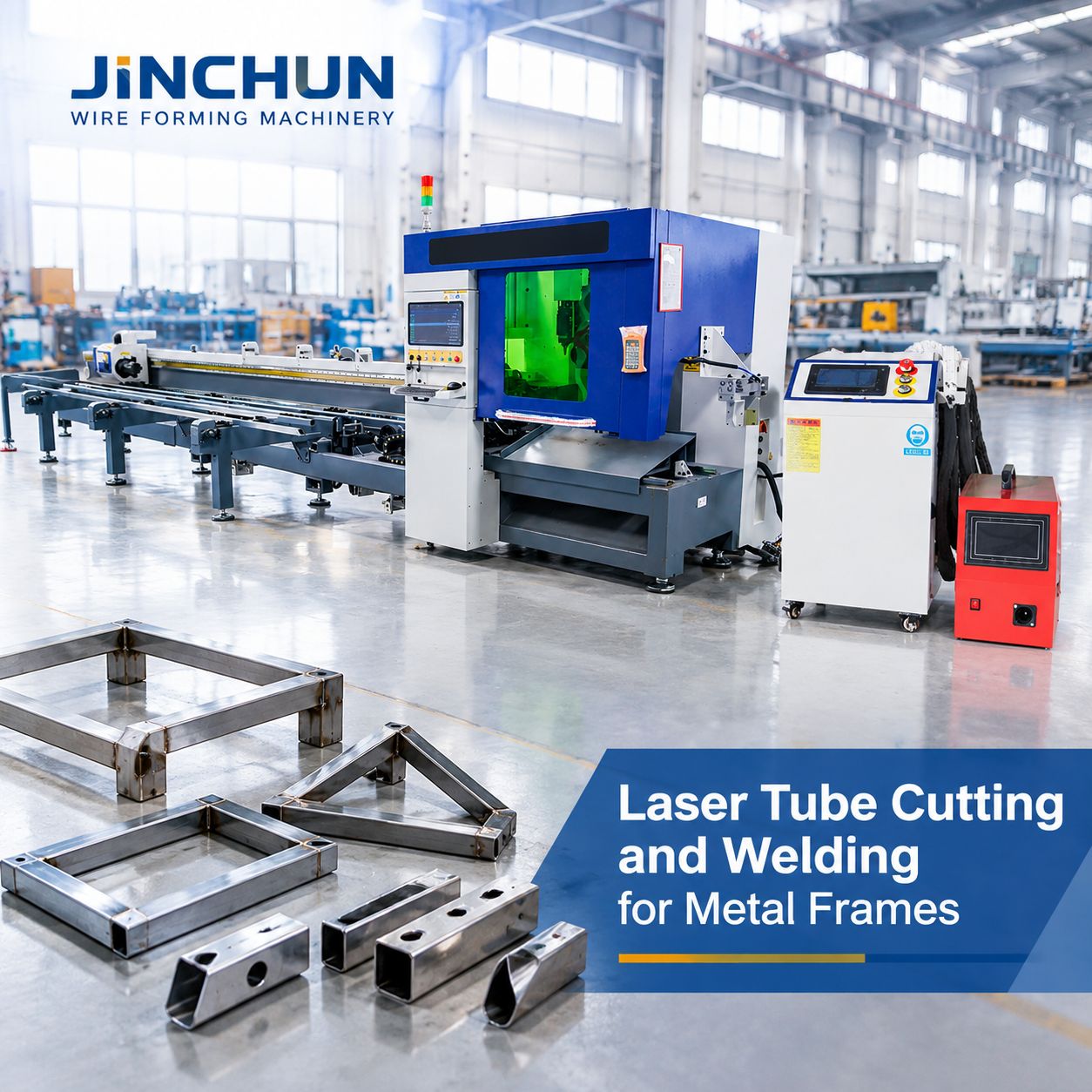
Producing a metal frame requires more than cutting tubes to the correct length and joining them together. The final assembly depends on how accurately each tube is prepared, how the connecting sections fit, and how consistently the welding process maintains the required geometry.
For manufacturers working with rectangular frames, equipment supports, furniture structures and other tubular metal components, coordinating laser tube cutting and welding is an important part of production planning.
A practical workflow should begin with the finished frame drawing. The drawing defines the overall dimensions, tube specifications, joint positions and assembly requirements. These details help determine the cutting operations, fixture design and welding sequence before equipment is selected.
By reviewing the complete production process rather than evaluating individual machines separately, manufacturers can build a more suitable workflow for metal frame production.
1. Review the Frame Drawing
The first step is to understand the complete frame structure. A technical drawing should identify the overall length, width and height, together with the dimensions and positions of individual tube sections.
Pay particular attention to the following details:
Overall frame dimensions and required tolerances.
Tube cross-sections, including round, square and rectangular profiles.
Connection positions between horizontal and vertical members.
Corner structures, branch connections and supporting sections.
Reference surfaces and assembly positioning points.
The relationship between individual components is especially important. Two tubes may have the correct individual lengths but still create an inaccurate assembly if their connection positions are inconsistent.
Establishing clear reference points helps coordinate cutting, positioning and welding. It also makes it easier to compare the finished frame against the original drawing during inspection.
2. Define Tube Cutting Features
Once the frame drawing has been reviewed, each tube section needs to be translated into a cutting requirement.
A laser tube cutting machine can be considered for processing tubular profiles with different cutting geometries, depending on the selected machine configuration and material specifications.
The cutting plan should cover several important features.
Tube length: Each section must be prepared according to its specified finished dimension. Length differences between matching components can affect frame symmetry and assembly positioning.
Holes and slots: Some frame designs require openings for fasteners, mounting brackets, cable routing or connecting components. Their positions should be referenced to consistent tube ends or drawing datums.
Joint cutouts: Tube intersections may require specially shaped ends to match the connecting member. The cut geometry should be reviewed according to the joint design and the required contact condition.
End preparation: Straight cuts, angled cuts and shaped ends serve different assembly purposes. The selected cutting process must produce the geometry needed for the following fit-up operation.
When evaluating a laser tube cutting machine, manufacturers should provide representative tube drawings, material information and cutting samples. Actual processing range, cutting capability, precision and cycle time should be confirmed against the selected machine configuration.
3. Check Fit-Up Before Welding
Cutting accuracy alone does not guarantee a satisfactory welded frame. The next step is to check how the prepared tubes fit together.
Fit-up refers to the positioning and contact condition of components before welding. It directly affects joint consistency and the ability to maintain the intended frame dimensions.
Three factors deserve particular attention.
Gap between components: Excessive or inconsistent gaps can influence weld formation and joint quality. The acceptable condition depends on the material, joint design and selected welding process.
Alignment: Connecting tubes should maintain the intended angles and reference positions. Misalignment can create uneven frame geometry or require additional correction during assembly.
Contact condition: The prepared surfaces should match the intended joint structure. Poor contact may result from incorrect cut geometry, material variation or inconsistent positioning.
A trial assembly using actual cut components is a useful way to identify these problems before production begins. Measurements and fit-up results should be recorded so that cutting and positioning requirements can be adjusted together.
4. Plan Fixtures and Welding Access
A suitable welding fixture helps maintain component positions throughout the joining process.
For metal frame production, fixtures may include a base support, locating blocks, positioning pins, adjustable stops and mechanical or pneumatic clamping devices, depending on the frame structure.
The fixture should establish reliable reference points for the main frame members. It should also prevent unnecessary movement when components are positioned and welded.
However, clamping strength is only one consideration. The fixture must also provide sufficient access for the welding operation.
Before finalizing the design, review:
Whether all components can be loaded in the correct sequence.
Whether locating points correspond to the drawing references.
Whether clamps interfere with the intended welding positions.
Whether the welding head can reach the required joints.
Whether the completed frame can be removed without damaging its structure.
For frames with multiple cross-members or intersecting tubes, the welding sequence should be considered during fixture design. A fixture that works for initial positioning may become difficult to use if later joints are obstructed by previously installed components.
5. Confirm the Welding Process
After cutting and fit-up have been validated, the welding process can be selected according to the actual material and joint requirements.
A laser welding machine is one option for joining compatible metal components. Its suitability should be evaluated through practical testing rather than assumed from the frame material alone.
Important factors include material type, tube wall thickness, joint geometry, surface condition and required weld appearance.
The welding process should be tested on representative samples before production. These trials help evaluate joint formation, penetration requirements, surface appearance and possible deformation.
For frames with multiple connection points, manufacturers should also consider the welding sequence. The order in which joints are completed can influence heat distribution and the movement of the assembled structure.
A suitable laser welding machine should therefore be evaluated together with the actual frame samples, fixture arrangement and welding requirements.
Machine configuration, laser power, applicable material range and processing performance should be confirmed through technical review and sample testing.
6. Inspect the Complete Frame
Inspection should cover the entire welded frame, not just the individual cutting and welding operations.
The first check is the overall geometry. Measure the finished length, width and height against the drawing. For rectangular structures, comparing the two diagonals is a practical method of identifying potential squareness deviations.
Other inspection points include:
Joint positions: Confirm that welded connections match their specified locations.
Frame alignment: Check whether the main members remain straight and correctly positioned.
Deformation: Look for distortion, twisting or changes in the frame geometry after welding.
Weld condition: Examine the appearance and continuity of the joints according to the required acceptance criteria.
Assembly compatibility: Confirm that mounting points and connecting sections fit their intended mating components.
Inspection results should be compared with the agreed drawing tolerances and product requirements. If deviations appear, the cause should be traced back to cutting, fit-up, fixture positioning or the welding sequence.
This approach helps manufacturers identify the actual source of variation instead of relying on repeated manual correction.
7. Record the Complete Workflow
A stable production process requires consistent information at every stage.
Manufacturers should establish a basic workflow record covering material preparation, tube cutting, component transfer, assembly positioning, fixture setup, welding and final inspection.
Useful records include tube specifications, cutting programs, component identification, fixture references, welding parameters and inspection results.
For repeat production, these records help operators reproduce the same processing sequence and identify changes when a new frame design is introduced.
Material handling should also be included in the planning process. Cut tubes should be identified and organized according to their assembly positions to reduce sorting errors and unnecessary handling.
When evaluating a complete production solution, manufacturers should consider how the cutting and welding equipment connect with the surrounding workstations. Material flow, available floor space, loading arrangements and finished-part removal can all influence the practical efficiency of the production line.
Conclusion
Successful metal frame production depends on the coordination of tube cutting, joint preparation, fit-up, fixture positioning, welding and final inspection.
A machine that performs well in an individual operation does not automatically guarantee a consistent finished frame. The complete workflow needs to be verified using representative drawings, actual materials and assembled samples.
Before selecting equipment, manufacturers should prepare the frame drawings and define the required dimensions, joint structures and production objectives. These details provide a practical basis for evaluating the appropriate cutting and welding configuration.
If you are planning a new metal frame production project or upgrading an existing process, contact Jinchun with your frame drawings, material specifications, tube dimensions and target production requirements. Our team can review your application and discuss suitable equipment configurations and production solutions.